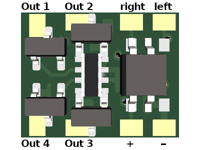
Load has to be connected between decoder + and the respective output.
It is strongly recommended to install a capacitor between decoder + and decoder – !!!
A DCC decoder is a tiny PCB with a MicroController used for model railroads. It gets DCC messages over the track, interprets them as commands and executes these.
There are motor (or loco) decoders, function decoders and accessory decoders. Motor and function decoders are mostly the same, but a function decoder can more or less only control simple on/off outputs. Motor decoders have also an H-bridge to fully control a DC motor in both directions.
Accessory decoders are for controlling switches, crossings and so on. (On our model railroad they are controlled over our own RailBus-Controlling-Network. (More on that topic later.))
You can get motor decoders for 20€ and more. (For 20€ you get a simple decoder: 1 motor & 2-4 function ouputs)
Function decoders start also at 20€. Then you get also 2-4 function outputs. But no motor output. So: What is the benefit to buy a function decoder if you can get a full loco decoder for the same price??
And if I built it myself: The costs will reduce down to 3-5€ (if it goes well…^^)
Plus: I can program all the functionalities which I want to have. And there are some of them, which are not provided by bigger manufaturers!
Load has to be connected between decoder + and the respective output.
It is strongly recommended to install a capacitor between decoder + and decoder – !!!
Nothing special happens: You can map all 29 functions to all 4 outputs.
You can save the subaddress to CV 31 and 32. (#31 high, #32 low byte.) To access the desired decoder, do the following:
In this mode you can set an address of another loco over the function buttons. The decoder will also react on messages sent to the loco.
| No | BIN | Name | Possible settings |
|---|---|---|---|
| 0 | 0000 | Off | |
| 1 | 0001 | Full brightness | CV 68 |
| 2 | 0010 | Dimmed brightness | CV 69 |
| 3 | 0011 | Speed as PWM | |
| 4 | 0100 | Blink pattern A | CV 71 - 75 |
| 5 | 0101 | Blink pattern B | CV 76 - 80 |
| 6 | 0110 | Fade in/out | CV 70 |
| 7 | 0111 | Fade 180° phase shifted | CV 70 |
Bit numeration:
1 Byte has 8 bits: bit 7 is most significant bit (msb) =128, bit 0 is least significant bit (lsb) =1. (76543210)
bit 7: 128
bit 6: 64
bit 5: 32
bit 4: 16
bit 3: 8
bit 2: 4
bit 1: 2
bit 0: 1
| CV | Description | Default value |
|---|---|---|
| 1 | Short address | 3 |
| 7 | Version | 1 |
| 8 | Manufactor ID (Write 8 for resetting the decoder) | 13 = DIY |
| 12 | Outputs used for acknoledgment bit 0: Output 1 bit 1: Output 2 bit 2: Output 3 bit 3: Output 4 |
bit 0: 1 = 1 bit 1: 1 = 2 bit 2: 0 = 0 bit 3: 0 = 0 =1+2 = 3 |
| 15 & 16 | Decoder Lock: CV 16: Decoder Lock Set distinct lock numbers for each decoder on one loco with the same decoder address (0 = motor, 1 = another decoder,…) CV 15: The key: Set CV15 to the loco on programming track and only that decoder where CV 15 equals CV 16 will apply on changes! |
CV 15 = 0 CV 16 = 0 |
| 17 & 18 | Long address | CV 17 = 0 CV 18 = 0 |
| 19 | Consist address | (set automatically) |
| 21 | Consist address active for F1-8 bit 0: F1, …, bit 7: F8 |
0 |
| 22 | Consist address active for FL,9-12 bit 0: FL_fwd, bit 1: FL_rev, bit 2: F9, …, bit 5: F12 |
0 |
| 0 (not implemented yet) |
||
| 29 | bit 0: Direction inverted? (0= normal, 1= inverted) bit 1: Is 28 steps mode? (0= 14 steps, 1= 28 steps) bit 3: Can listen to other address? (0= acts like normal decoder, 1= can also react on messages to other decoders) bit 4: Using subaddress? (0= acts like a normal decoder, 1= using subaddresses) bit 5: Is my address a Long Address? (0= My address is short (CV1), 1= My address is long (CV 17&18)) bit 6: Are special effects enabled? (0= off, 1= on) bit 7: not used. |
bit 0: 0 = 0 bit 1: 1 = 2 bit 2: 0 = 0 bit 3: 0 = 0 bit 4: 0 = 0 bit 5: 0 = 0 bit 6: 1 = 64 bit 7: 0 = 0 =0+2+0+0+0+64+0 = 66 |
| 31 & 32 | If subaddress is used, this subaddress is stored here: CV 31: Subaddress high byte CV 32: Subaddress low byte Note: both CVs are also used to store the Other Address configuration! Here CV 31 stores F28 (in bit 7) down to F21 (in bit 0) and CV 32 stores F20 (in bit 7) down to F13 (in bit 0) |
CV 31 = 0 CV 32 = 0 |
| 34-62 | Function - Output - Mapping Which function activates which output? bit 0: Output 1 bit 1: Output 2 bit 2: Output 3 bit 3: Output 4 F0: CV 34 … F28 : CV 62 |
CV 34 = 2+1 = 3 (F0 activates Output 1 and 2) CV 35-62 = 0 |
| 63-67 | Output - Default Effect - Mapping Which effect shall be applied? bit 7 to 4: Forwards direction bit 3 to 0: reverse direction Output 1: CV 63 … Output 4: CV 66 |
CV 63: 0x20 = 0b 0010 0000 = 32 -> in Forward: Dimmed CV 64: 0x02 = 0b 0000 0010 = 2 -> in Reverse: Dimmed CV 65 - 67 = 0 |
| Effect settings | ||
| 68 | Brightness of full light (effect 1) (0-255) |
255 |
| 69 | Brightness of dimmed light (effect 2) (0-255) |
50 |
| 70 | Cycle time of fading (effect 6 & 7) in 10th of a second (0-255) |
15 = 1.5 sec |
| 71 - 80 | On & off times for blink pattern A and B (effect 4 & 5)order Blink A | Blink B1 off-time 71 | 762 ON -time 72 | 773 off-time 73 | 784 ON -time 74 | 795 off-time 75 | 80 |
CV 71 = 0: no off at start CV 72 = 1: 0.1s on CV 73 = 1: 0.1s off CV 74 = 1: 0.1s on CV 75 = 10: 1s off CV 76 = 0: no off at start CV 77 = 2: 0.2s on CV 78 = 2: 0.2s off CV 79 = 2: 0.2s on CV 80 = 2: 0.2s off |
| 118 - 128 | Function memory for analog and subaddress mode. | |
| 129 - 255 | Special Effects | see special effects programming chapter |
This area contains lists of rules of effects, which shall be applied to outputs if a function is on. There are only 4 regulations in this area:
We will see how it works, when we have a look to the default values:
CV 129: 195 In binary: 11 000011. (Separated in flags, function number)
The last 6 bits (000011 = 3) say: This rule is for function 3.
bit 7 = 1: This rule applies if F4 is active on my address. (The address of the decoder)
bit 6 = 1: This rule also applies if F4 is active on the other address, which the decoder is maybe listening to. (Only if other-address-mode is active)
CV 130: 18 In binary: 0 001 0010. (Separated in direction, effect, output mask)
bit 7 = 0: This is only for reverse direction
bit 6-4 = 001: Apply effect 1: full brightness
bit 3-0 = 0010: Apply this effect on output 2. (bit 0: Output 1, bit 1: Output 2, bit 2: Output 3, bit 3: Output 4)
CV 131: 145 In binary: 1 001 0001. (Separated in direction, effect, output mask)
bit 7 = 1: This is only for forward direction
bit 6-4 = 001: Apply effect 1: full brightness
bit 3-0 = 0001: Apply this effect on output 1. (bit 0: Output 1, bit 1: Output 2, bit 2: Output 3, bit 3: Output 4)
CV 132: 0
Separator: End of rule
CV 133: 196 = Which Func: 11 000100 => my ot F4
CV 134: 35 = Output: 0 010 0011 => in Reverse: Effect 2 on Output 1 and 2 (=Dimm on 1 & 2)
CV 135: 163 = Output: 1 010 0011 => in Forward: Effect 2 on Output 1 and 2 (=Dimm on 1 & 2)
CV 136: 0 = separator
CV 137: 133 = 10 000101 => my F5
CV 138: 1 = 0 000 0001 => in Reverse: Effect 0 on Out 1 (Off on 1)
CV 139: 129 = 1 000 0001 => in Forward: Effect 0 on Out 1 (Off on 1)
CV 140: 0 = separator
CV 141: 134 = 10 000110 => my F6
CV 142: 2 = 0 000 0010 => in Reverse: Effect 0 on Out 2 (Off on 2)
CV 143: 130 = 1 000 0010 => in Forward: Effect 0 on Out 2 (Off on 2)
CV 144: 0 = separator